Step 1:
 Adding situational context to your renderings always helps to make them appear more real and convincing. This tutorial will take you through the steps needed to add people to a rendered image.
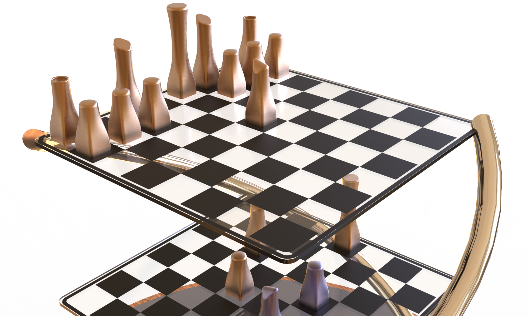
 Begin by selecting a realistic view of your assembly in SolidWorks. Render this view to ensure the scale and angle are appropriate. Check that details and materials appear as intended. Wood grain and other materials with distinct textures should be appropriately scaled.
Step 2:
Select a Lighting Setup for your scene that throws realistic shadows onto the ground plane. Changing lighting schemes in SolidWorks is simple.
From the PhotoWorks Menu click Scene. The Scene Editor window will open. Click on the Lighting tab and then the Select Lighting scheme button. From there you can view previews of many kinds of lighting schemes. Double click to select.

Step 3:


Now you need to define the type of ground surface your assembly will sit on.
From the Scene Editor window click on the Room tab.
In the bottom half of the window, you will see a list of the bounding surfaces that make
up the space in which your assembly is rendered. By clicking on the button with the
three dots you can change the material of the surface.
Applying the material is done with the same interface as applying a material to a part.
Once you have made a selection, click the Apply button in the Scene Editor.
Step 4:


The next step will require you to render the scene to a JPEG. Open this image in Photoshop. Create a new layer. This is where we will begin to bring people into the scene.
Open your source file for Entourage components. Once you have chosen a figure, click on the corresponding image layer. Select all and copy.
Go to the empy new layer in your assembly scene file. Paste.
You will now need to size the figure appropriately.
Edit menu>Transform>Scale.
Step 5:

After you have scaled and placed the figure, you need to create a shadow.
Begin by copying the figure layer. Using the Free Transform tool (Ctrl+T), rotate and reshape the figure to become a shadow. Use the shadow cast by your assembly as a guide to angle and length.
Once that layer is set, fill it with black. Then blur it.
Filter>Blur>Gaussian Blur.
All that is left to do is to adjust the opacity of the layer until the
figure’s shadow has the same density as the assembly’s shadow.


Step 6:
These steps can be repeated with other figures and also with trees and shrubs.
Make sure that you do not add so many elements that the assembly becomes overwhelmed.
Keep in mind that you can use Photoshop filters and effects to reduce the photorealism of the elements.


